What Is Graph Engineering? Nodes, Edges, and State in Agent Workflows
A plain breakdown of graph engineering for agents: what a node actually bounds, what an edge is allowed to do, and how shared state moves between them.
Table of Contents
A workflow diagram tells you how an agent is supposed to run. It says nothing about what actually happened the last time state got corrupted mid-graph.
Most agent failures do not happen because a model gave a bad answer. They happen because a node wrote a malformed field into shared state, an edge routed on a value that was already stale, or two parallel branches wrote to the same key at once. Graph engineering is the discipline of designing around exactly that: making every node, every transition, and every piece of shared state explicit enough to inspect, test, and fix.
This post gives you a working definition of graph engineering, a rigorous breakdown of nodes, edges, and state, and the part most guides skip: how you actually catch it when a graph misbehaves in production. If you want the LangGraph-specific implementation of these ideas, see what LangGraph is and how its state graphs work.
What Is Graph Engineering?
Graph engineering is the practice of designing an agent’s execution as an explicit graph instead of one open-ended reasoning loop. You define the nodes that can run, the edges that connect them, and a shared state object that every node reads from and writes to.
The alternative is a single agent loop that decides its own next step every time, with no fixed structure to compare against. That flexibility is useful for open-ended research tasks. It becomes a liability the moment you need to know why a run went wrong, because there is no expected shape to check the actual run against.
A graph gives you that expected shape. You can point at a specific node and ask what it should have produced, point at a specific edge and ask whether it routed correctly, and point at state after any step and ask if it matches what the graph should have written there.
Nodes: The Bounded Execution Units of a Graph
A node is a single, bounded unit of work. It takes the current state as input, does one job, an LLM call, a database query, a tool invocation, a human approval step, and returns an update to that state. Nothing else about the graph is its concern.
That boundary is what makes a node testable. You can call a node with a fixed state snapshot and check its output against an expected result, the same way you would unit test a function, because a well-designed node has no hidden dependency on anything outside the state it was handed.
Nodes fail in a small number of predictable ways. A node can return a malformed shape that the next node cannot parse. It can time out and leave a partial write in state. It can succeed on its own terms while still returning something the rest of the graph cannot use, which is the hardest failure to catch because nothing throws an error.
Take a support-ticket graph as a concrete example. A classifier node reads the incoming ticket and writes a category field. A retrieval node reads that category and pulls relevant documents. A writer node reads the retrieved documents and drafts a reply. Each node is bounded to one job, and each one only knows about the state it was actually handed.
Why Node Boundaries Matter More Than Node Count
Teams often assume more nodes mean more granularity and more granularity means better observability. That is only true if each node’s boundary is actually narrow. A node that quietly does three unrelated things inside one function call gives you one span with three jobs tangled together.
The fix is not adding more nodes for their own sake. It is making sure each node’s input and output are specific enough that a failure inside it points at one clear cause, not a paragraph of mixed responsibilities you now have to untangle by hand.
Edges: How Work Actually Moves Through the Graph
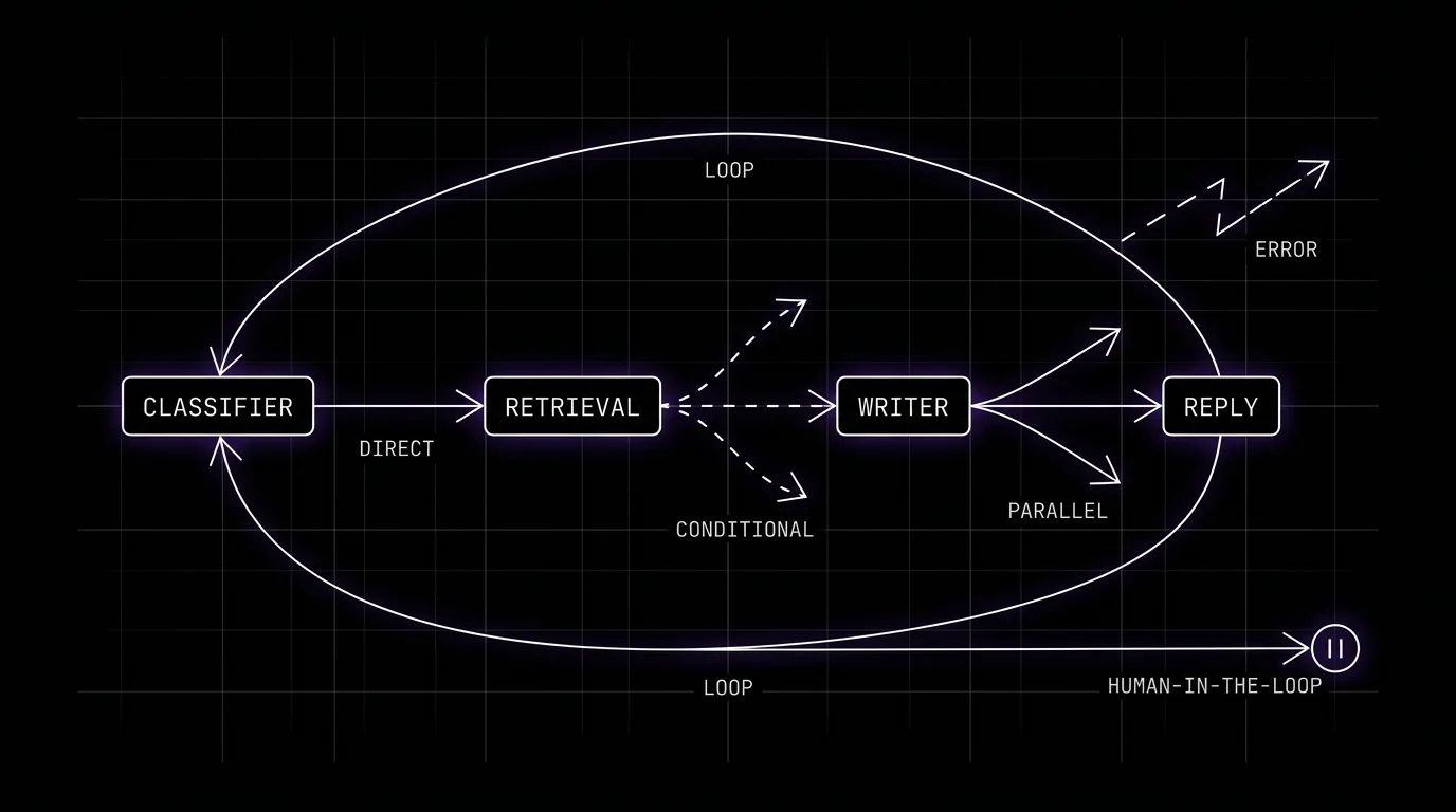
An edge decides which node runs next. The simplest edge is direct: node A finishes, node B always runs after it. Most production graphs need more than that, and the edge types you choose determine how much control you actually have over a run.
Conditional edges read the current state and pick a branch based on it, like routing to a specialist node when a classifier’s confidence is low. Parallel edges fan a single state out to multiple nodes at once, which is fast but introduces the question of how their separate writes get merged back together. Loop edges send execution back to an earlier node, common in review-and-revise patterns where a draft gets checked and sent back until it passes. Error edges catch a node’s failure and route to a fallback or a retry instead of letting the whole graph crash. Human-in-the-loop edges pause the graph entirely and wait for external approval before continuing.
| Edge type | What decides the next node | Where it typically appears | Main failure risk |
|---|---|---|---|
| Direct | Fixed, always the same next node | Simple linear pipelines | None on its own, brittle if the sequence needs to change |
| Conditional | A rule evaluated against current state | Routing to a specialist or fallback node | Routes on stale or incomplete state |
| Parallel | Fan-out to multiple nodes at once | Independent sub-tasks run together | Conflicting writes when branches rejoin |
| Loop | Sends execution back to an earlier node | Draft-review-revise cycles | Runs forever without a stop condition |
| Error | Triggered by a node’s failure or exception | Retries and fallback paths | Masks a real failure as a handled one |
| Human-in-the-loop | External approval or input | High-stakes or irreversible actions | Graph left waiting with no timeout |
The Difference Between a Graph and a Simple Sequence
A plain sequence only has direct edges. What actually makes something a graph, rather than a chain with extra steps, is the presence of conditional or loop edges, because those are what let the same state produce different paths on different runs.
That branching is also where most debugging time goes. A linear pipeline fails the same way every time it fails. A graph with conditional routing can take a dozen different valid paths, and the one that broke is not always the one you tested last.
Guard Conditions Keep Edges From Firing on Bad Data
A guard condition is a check an edge runs before it commits to a route, separate from the routing rule itself. Instead of trusting a confidence score blindly, a guard can confirm the field actually exists and falls inside an expected range before the edge acts on it.
Without a guard, an edge that reads a missing or malformed field can route to the wrong branch with no warning, because the edge logic itself never checked whether the input it was reading was even valid in the first place. Adding that check catches the failure at the edge instead of two nodes downstream.
State: The Shared Record Every Node Reads and Writes
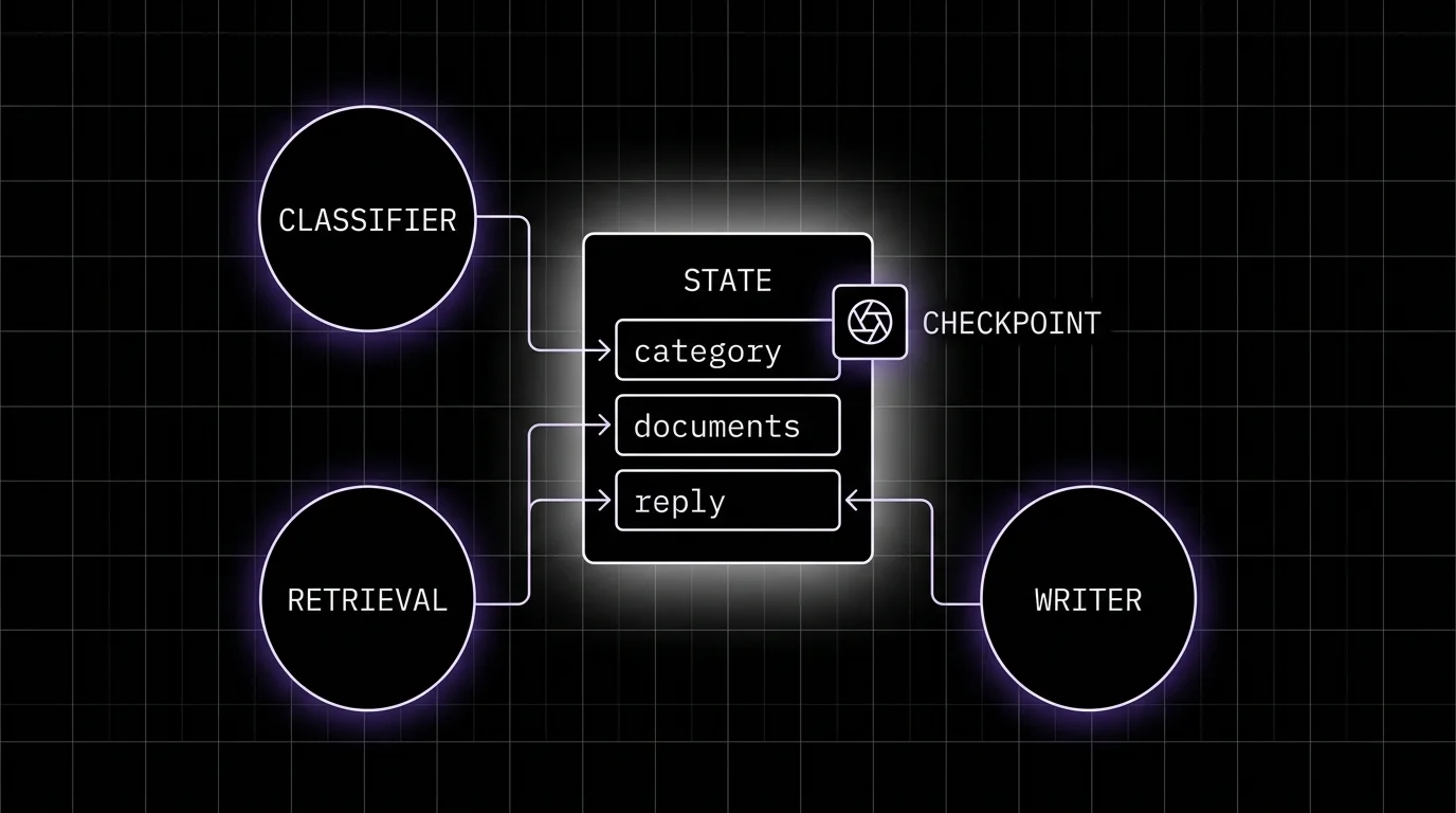
State is the typed object that carries data through the graph. Every node reads part of it on the way in and writes part of it on the way out, and it is the one piece of the system every node has in common.
Treat state like a schema, not a scratchpad. Define exactly which fields exist, what type each one holds, and which nodes are allowed to write to which fields. A graph where any node can write any key looks flexible early on and becomes impossible to debug once three different nodes have quietly written to the same field for different reasons.
In the support-ticket example, the classifier owns the category field, retrieval owns the documents field, and the writer owns the reply field. If the writer node were allowed to overwrite category too, a bug in the writer could silently change how the ticket gets routed on the next pass, with no error anywhere pointing at the actual cause.
State Reducers Resolve What Happens When Writes Collide
A reducer is the rule that decides how two updates to the same field combine. Without one, a parallel branch’s write silently overwrites another branch’s write, and whichever node finished last wins by accident rather than by design.
Common reducers append to a list instead of replacing it, take the higher of two confidence scores, or merge two dictionaries key by key. The reducer you pick is a real design decision. Getting it wrong does not throw an error, it just quietly loses data.
Checkpoints Turn State Into Something You Can Resume From
A checkpoint is a snapshot of state saved after a node runs. With checkpoints in place, a graph that fails partway through does not have to restart from scratch. It can resume from the last good snapshot, or pause indefinitely for a human-in-the-loop edge and pick up exactly where it left off.
Checkpoints also make replay possible. If a run produced a bad result, you can load the state at any checkpoint and re-run the graph from that point with a different prompt or model, which turns a one-off failure into something you can actually reproduce and fix.
Common Graph Patterns You Will Actually Build
Most production graphs are variations on a small set of patterns, not bespoke topologies invented from scratch. Recognizing which one you are building tells you which edge types and state design you actually need.
| Pattern | Structure | Best fit |
|---|---|---|
| Prompt chaining | Fixed sequence of direct edges | Multi-stage tasks with a known, unchanging order |
| Routing | One conditional edge splits into specialist branches | Requests that need different handling by type |
| Parallelization | Fan-out to independent nodes, then merge | Independent sub-tasks that don’t depend on each other |
| Orchestrator-worker | One node assigns work, workers execute, results return | Variable-sized task lists decided at runtime |
| Evaluator-optimizer | A loop edge sends output back for revision | Draft-and-critique cycles with a quality gate |
| Human-in-the-loop | An edge pauses for external approval | Actions with real cost if they are wrong |
Picking the wrong pattern for the job is a common source of unnecessary complexity. A routing task forced into a parallelization pattern runs every branch and throws most of the work away, and an evaluator-optimizer loop without a stop condition can burn through a token budget on a task that needed one clean pass.
Most production graphs also combine two or three of these patterns rather than picking exactly one. A support workflow might route by ticket type, then fan out to a parallel retrieval step, then loop a drafted reply through one evaluator-optimizer pass before a human-in-the-loop edge approves anything that touches billing.
Why Do Graph-Based Agents Still Fail in Production?
A correctly diagrammed graph is not a reliable one. Diagrams show topology, the boxes and arrows, and topology is not the layer where most production failures actually live. State is.
A node can write a field that technically parses but is semantically wrong, a category that looks valid but does not match the input. A conditional edge can route correctly on the value it received while that value was already stale by the time the edge evaluated it. A reducer can merge two parallel writes into something neither branch intended, and the graph keeps running because nothing about that merge raised an exception.
None of these show up in a static diagram of the workflow, because a diagram only proves the graph is structurally sound. It says nothing about whether last Tuesday’s run actually behaved that way, which is the question that matters once the graph is in production.
What a Diagram Cannot Tell You That a Trace Can
A diagram shows every path a graph is allowed to take. It cannot show you which path a specific run actually took, what state looked like at each step along that path, or where a value first went wrong. That gap is exactly what tracing a graph’s execution is for.
Reading a trace instead of a diagram turns “the graph is supposed to route to the specialist node when confidence is low” into a checkable fact: did this run’s edge decision match that rule, given the state it actually had at that point. A diagram can only tell you the rule exists.
Future AGI
Future AGI’s tracing captures each node in a graph-based workflow as its own span inside one trace, so a run through a graph shows up as the sequence of node calls, tool calls, and edge decisions behind it, not one opaque block (Observe docs). Because scores attach to a single span as easily as to a whole trace, a node’s output can be checked on its own terms instead of only through the graph’s final answer.
For the sequencing itself, Trajectory Match compares an agent’s actual node sequence against an expected trajectory, with strict mode scoring the matching prefix in order, which catches a graph that took a wrong branch even when its final output still reads fine (Trajectory Match docs). That is a direct check on whether an edge routed the way the graph was designed to.
Beyond the built-in checks, custom evals let you score a specific node’s output against whatever a given graph actually needs to get right, a state field’s format, a routing decision’s correctness, a reducer’s merge result, rather than relying only on a generic pass or fail at the end of the run. Future AGI’s tracing also instruments LangGraph directly, so node, edge, and state-graph spans from a LangGraph workflow arrive without custom instrumentation code.
When a node fails the same way across many runs, Error Feed scans traces in an Observe project, groups the ones that failed the same way into a single issue, and points at the fix layer the problem actually belongs to, rather than leaving you to notice the pattern across a hundred separate incidents on your own (Error Feed docs).
Conclusion
Nodes bound the work, edges decide what happens next, and state is what actually breaks when a graph misbehaves. Most guides stop at the diagram, because a diagram is where the design gets easy to explain and hard to be wrong about.
Production is where a diagram stops being enough. Score nodes on their own output, check that edges took the path they should have, and validate state after every write, because a graph that only gets checked at its final answer will hide exactly the failures graph engineering was supposed to make visible.
Frequently Asked Questions
What is graph engineering in AI agent workflows?
What is the difference between a node and an edge in a graph engineering context?
Is graph engineering the same as LangGraph?
Why do graph-based agents still fail after the workflow is diagrammed correctly?
How do you evaluate a graph-based agent workflow in production?
LangGraph is an MIT library for stateful agent graphs. Learn what LangGraph is and how StateGraph, nodes, edges, reducers and checkpointers work in version 1.x.

Trace, debug, evaluate multi-agent AI systems 2026 with traceAI, OpenTelemetry spans, rubric scoring. Code, span tree, three real failure cases.
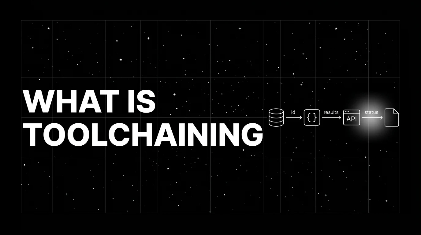
Toolchaining is the discipline of composing multi-step tool calls in an agent: state passing, error propagation, parallel vs sequential, fine-tune line.